
Network hardware forms the physical backbone of IT infrastructure, directing data packets between local devices, external networks, and untrusted zones. Switches, routers, and firewalls operate at distinct layers of the OSI (Open Systems Interconnection) model to segment traffic, determine optimal routing paths, and block unauthorized access.
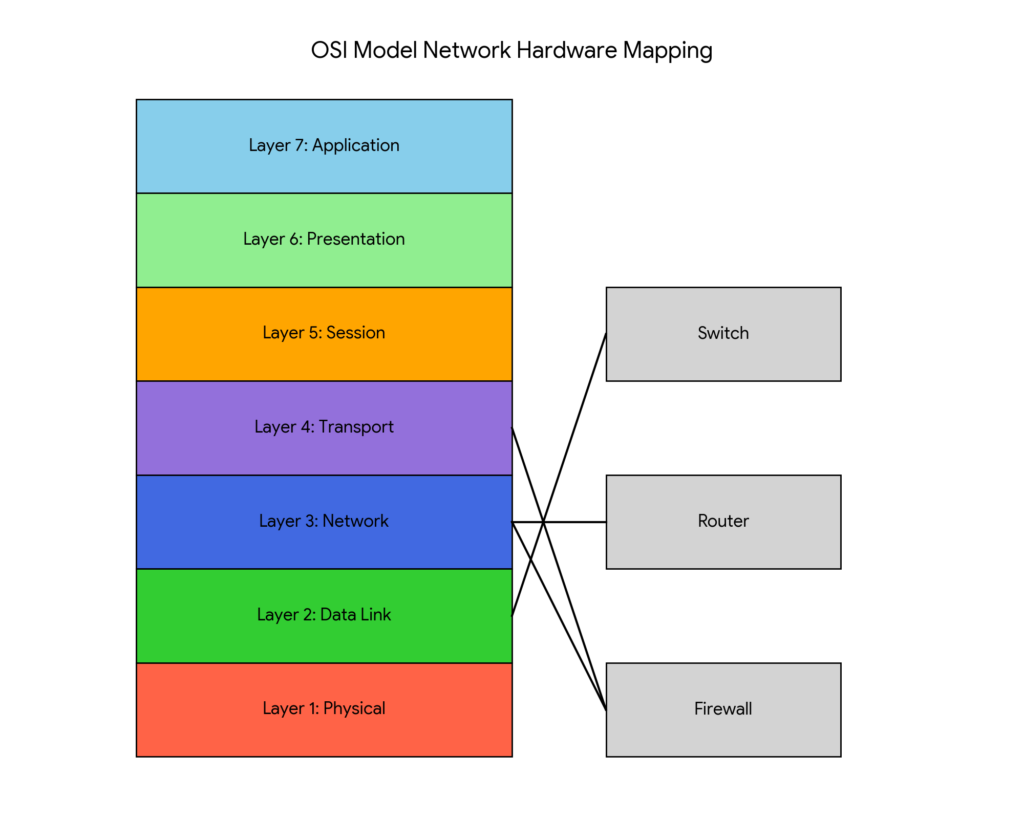
Switches: Layer 2 Local Traffic Forwarding
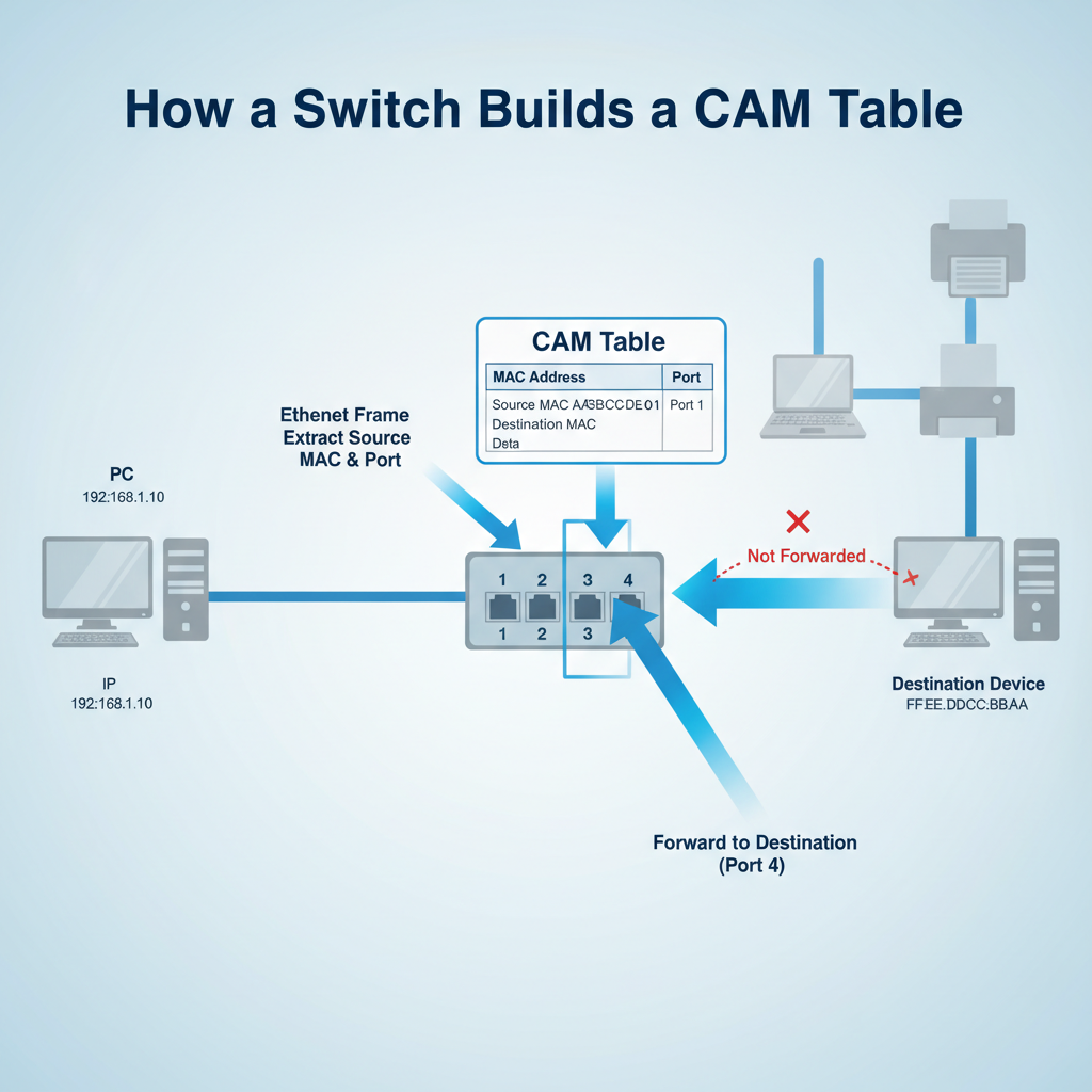
Switches operate at Layer 2 (Data Link Layer) of the OSI model, governing traffic within a single Local Area Network (LAN). When a network device powers on and transmits data, the switch reads the source Media Access Control (MAC) address—the unique physical identifier burned into the device’s network interface card.
The switch records this MAC address and maps it to the physical port where the device connects, storing this mapping in a Content Addressable Memory (CAM) table. When a new data frame arrives, the switch examines the destination MAC address, consults the CAM table, and forwards the frame exclusively out of the specific port tied to that destination. This microsegmentation prevents data collisions and preserves bandwidth by isolating traffic flows.
Routers: Layer 3 Path Determination
While switches connect devices within the same network, routers operate at Layer 3 (Network Layer) to connect disparate networks together—such as linking a corporate LAN to the public Internet. Routers ignore physical MAC addresses and instead analyze logical Internet Protocol (IP) addresses.
When a router receives a packet destined for an external network, it strips away the Layer 2 framing to expose the Layer 3 IP packet. The router inspects the destination IP address and queries its internal routing table—a database of known network pathways and their associated metrics.
text
# Simplified IPv4 Routing Table
Destination        Gateway            Flags   Interface
0.0.0.0/0          198.51.100.1       UG      eth0 (Default route to Internet)
192.168.1.0/24     0.0.0.0            U       eth1 (Directly connected LAN)
The router calculates the most efficient path, re-encapsulates the IP packet into a new Layer 2 frame appropriate for the outbound interface, and forwards it to the next hop. Differentiating between Layer 2 MAC forwarding and Layer 3 IP routing represents a core objective for IT professionals studying How to Pass CompTIA A+ Core 1 (220-1201).
Firewalls: Perimeter Defense and Stateful Inspection
Firewalls sit at the boundary between trusted internal networks and untrusted external networks, operating primarily at Layer 3 and Layer 4 (Transport Layer). Administrators configure firewalls with Access Control Lists (ACLs)—sequential rulesets that explicitly permit or deny traffic based on IP addresses, protocol types, and port numbers.
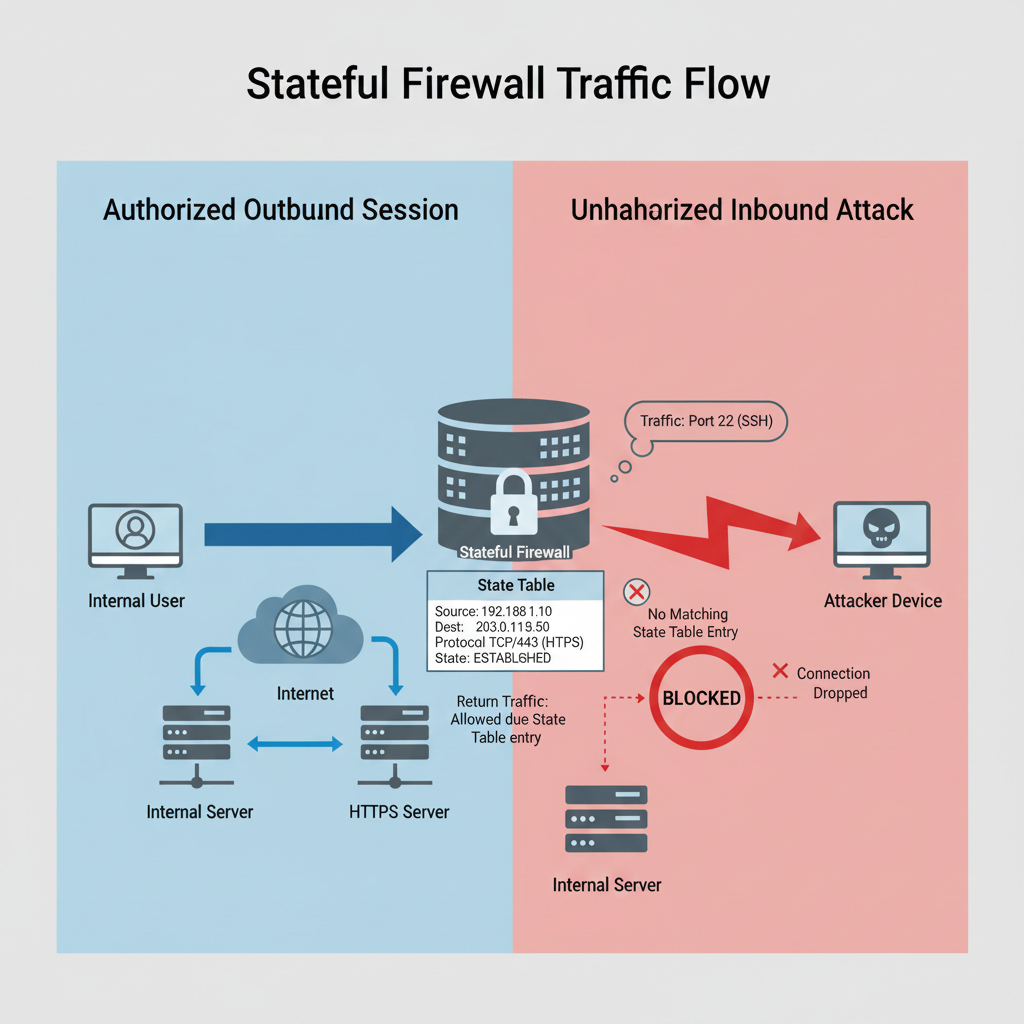
Modern hardware firewalls utilize stateful inspection. Instead of merely checking individual packets against a static list, a stateful firewall dynamically tracks the active state of every network connection in a state table.
text
# Example Firewall ACL Logic
Rule 1: PERMIT TCP SOURCE 192.168.1.0/24 DESTINATION ANY PORT 443
Rule 2: DENY IP SOURCE ANY DESTINATION ANY (Implicit Deny)
If an internal user initiates an outbound HTTPS (Port 443) connection to a web server, the stateful firewall records the session. When the web server replies, the firewall recognizes the returning packets as part of an established, permitted session and allows them through the perimeter. If an external attacker attempts to send uninitiated inbound traffic, the firewall finds no matching state table entry and immediately drops the packets.
Leave a Reply